
0
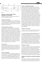
Owner's of the Klipsch Stereo Amplifier RSA-500 gave it a score of 0 out of 5. Here's how the scores stacked up:

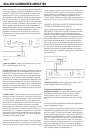
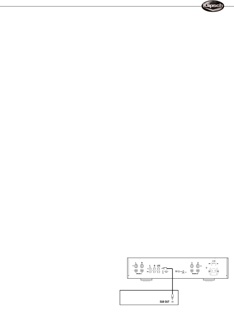
REAR PANEL INPUTS AND OUTPUTS
/CONNECTIONS AND SETUP
Make all connections with the power turned “OFF” on both
the subwoofer amplifier and your receiver or preamplifier!
1. Speaker Level Inputs
The Speaker Level inputs which allow this amplifier to be used in
whole house distributed audio systems or with receivers that do
not feature line or subwoofer outputs. You may connect either
the inputs or outputs with Banana or pin connectors as well as
stripped wire up to 12 gauge.
2. Line Level Inputs and Outputs
The Line Level inputs consists of a pair of stereo jacks and a
single LFE RCA phono jack. Either one or both of the stereo jacks
may be used. (Use a shielded, high quality subwoofer
interconnect cable of appropriate length with RCA plugs on each
end. Your dealer can help you select a suitable cable.) Use
the LFE jack when you are using the crossover built into your
receiver or processor.The stereo inputs should be used when
you wish to utilize the crossover built into the RSA-500. The Line
Level outputs consist of a pair of gold plated stereo RCA jacks
and a single LFE RCA phono jack. This set of outputs are unfil-
tered pass through for both the Line Level and LFE input signals.
They can be used to connect to a second RSA-500 amplifier or
to connect back to your electronics if needed.
3. Phase Control
The Phase control on the RSA-500 is switchable between either
0˚ or 180˚. This control allows you to fine tune the performance
of your subwoofer system by optimizing the blend with the main
speakers. One of the positions may result in an audible increase
in bass output depending upon room placement.
4. Equalizer Selection
The Equalizer switch has four settings which are labeled 1
through 4. In the “1” position, the EQ curve selected is opti-
mized for the RW-5802 in-wall subwoofer. In the “2”position,
the EQ curve selected is optimized for the AW-800-SW outdoor
subwoofer. The position labeled “3” is for future use.The
position labeled “4” is for future use.
5. Power Mode Selection
The Power Mode switch has three settings – “Trigger”,“Auto”
and“On”. In the “Trigger” position, leave the Master Power switch
in the “On” position and set the Power Mode switch to the
“Trigger” position, then the amplifier will automatically turn itself
on and off when 5-30 volts DC is detected or removed from the
rear panel 1/8" Trigger jack. Tip is positive, ring is negative.
There is no delay when using the Trigger function. In the “Auto”
position, leave the Master Power switch in the “On” position and
set the Power Mode switch to the “Auto” position, then the
amplifier will automatically turn itself on and off when an audio
signal is detected or removed from the rear low or high level
inputs. There is a 2 second On delay and a 15 minute Off delay
when using the Auto Power function. In the “On” position, the
Master Power switch turns the amplifier on or off. Set the Master
Power switch to the “On” position and set the Power Mode
switch to the “On” position, then the amplifier will turn itself on
and off with the Master Power switch.
6. Speaker Level Outputs
The Speaker Level outputs may connected either with Banana or
pin connectors as well as stripped wire up to 12 gauge.
7. AC Line Cord and Main Switch
The AC Line connection uses a detachable two-prong power
cord. Insert the line cord into this jack, set the Master Power
switch located above the cord to “Off”, then insert the power
cord into an appropriate AC receptacle. Leave the Master Power
switch off until all connections are completed. (We recommend
leaving the Master Power and Power Mode switches in the “On”
position for normal operation in most systems.)
CONNECTIONS AND ADJUSTMENTS
The RSA-500 is a high-performance, power amplifier with a
built-in subwoofer crossover. It is designed specifically to drive
one or two subwoofer modules, such as the RW-5802, to maxi-
mum output without audible distortion or risk of damage.
Although the amplifier’s connections and controls are simple,
their use varies somewhat according to the subwoofer system’s
application. Typical setup procedures are described in the
following sections – one for digital systems and one for
analog systems.
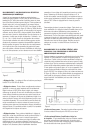
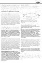
DIGITAL SURROUND RECEIVER OR
PROCESSOR CONNECTIONS
Today’s Dolby Digital
®
and DTS
®
digital surround receivers and
processors, as well as all THX-certified models, have line-level
subwoofer outputs and built-in subwoofer crossovers. If your
system is built around one of these, it will almost always be best
to use the RSA-500’s LFE input.This will bypass the crossover
and level controls (Figure 3). Use a shielded, high quality sub-
woofer interconnect cable of appropriate length with RCA plugs
on each end. Your dealer can help you select a suitable cable. Be
sure to go into your receiver or processor’s speaker setup menu
and set Subwoofer to “On” or “Yes” in the subwoofer menu.Your
receiver or processor may have additional bass management
abilities beyond simply activating the subwoofer output. Consult
your receiver or processor’s owner’s manual or your dealer for
more information on the proper bass management settings for
your system.
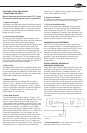
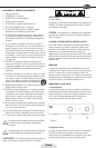
• Crossover Adjustment – When the RSA-500’s LFE input is
used, the crossover control will not function.
Figure 3


Find Your Products By Category
Please Login
